Introduction
A slewing bearing — also called a slewing ring or turntable bearing — is a large-diameter rolling-element bearing capable of handling simultaneous axial, radial, and moment loads. You’ll find them in excavators, tower cranes, wind turbine yaw systems, radar antennas, and tunnel boring machines. Selecting the wrong slewing bearing leads to premature failure, costly downtime, and in the worst case, catastrophic equipment collapse. This guide walks you through load calculation, gear type selection, sealing, mounting, and failure prevention — so you specify the right ring every time.
What Is a Slewing Bearing?
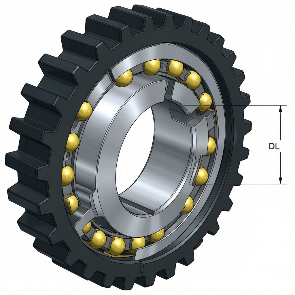
Unlike a standard deep groove ball bearing that handles primarily radial loads, a slewing bearing features a large inner ring with an internal or external gear, rolling elements (balls or crossed cylindrical rollers), and either a single-row or multi-row raceway configuration. The defining characteristic is its ability to handle overturning moment loads — the rotational force that tries to tip the structure over.
Common configurations include:
- Single-row four-point contact ball — most common, good for medium loads
- Double-row ball — higher load capacity than single-row
- Crossed cylindrical roller — highest rigidity, precision applications (robotics, machine tools)
- Three-row roller — heaviest loads, mining and heavy construction
- Wire race — lighter, custom shapes, aerospace and medical
Load Calculation: Axial, Radial, and Moment Loads
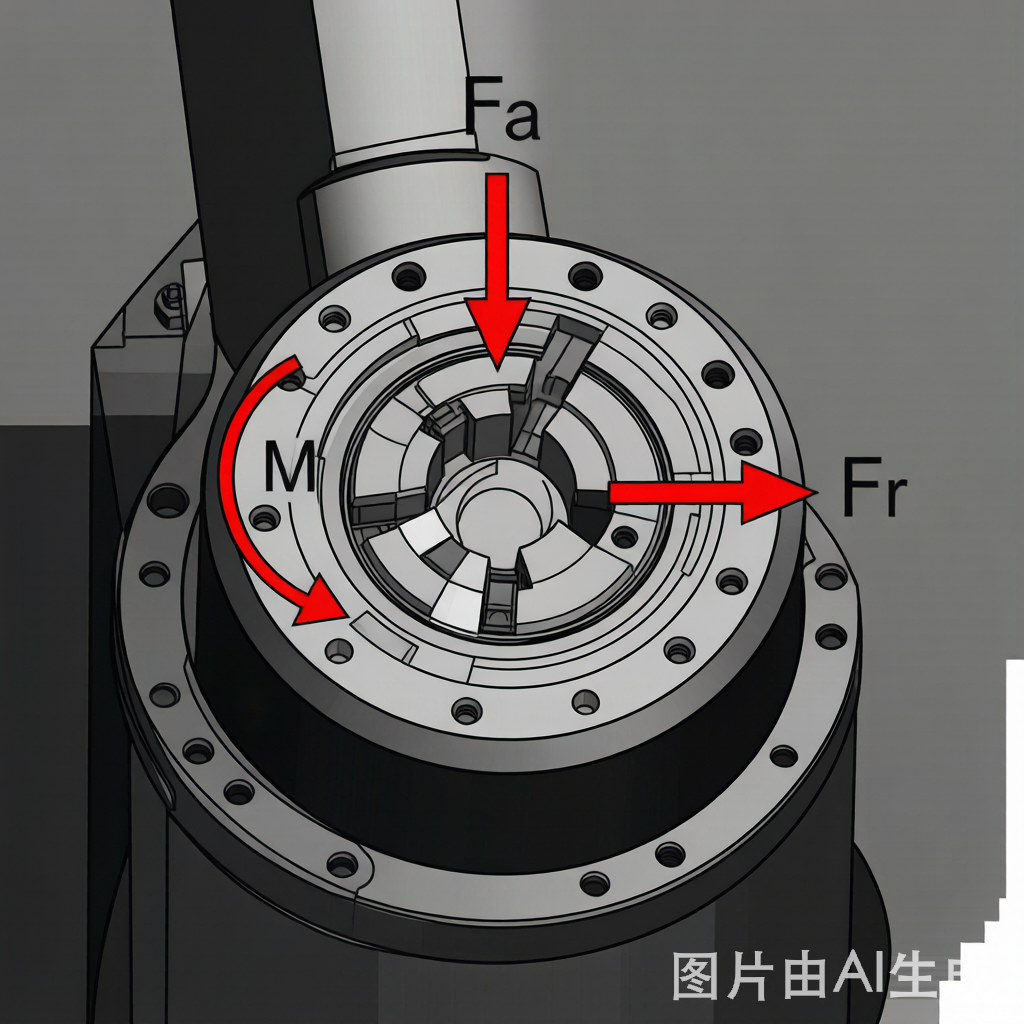
Slewing bearings are selected based on three simultaneous load components:
- Axial load (Fa) — force parallel to the rotation axis (e.g., the weight of the excavator cab)
- Radial load (Fr) — force perpendicular to the rotation axis (e.g., digging reaction forces)
- Overturning moment (M) — the rotational force from an off-center load (e.g., a crane boom under load)
The combined equivalent load is calculated using the formula: Fa’ = Fa + k × (4M/DL) + 2.5 × Fr, where DL is the bearing’s raceway diameter and k is a configuration constant (typically 0.75 for four-point contact).
Most manufacturers publish static load rating curves. You plot your (Fa, M) operating point on the curve — if it falls below the limit line, the bearing is adequate. Always apply a safety factor of 1.2–1.5, and higher (2.0+) for critical lifting applications.
Gear Type Selection: Internal vs External vs Non-Geared
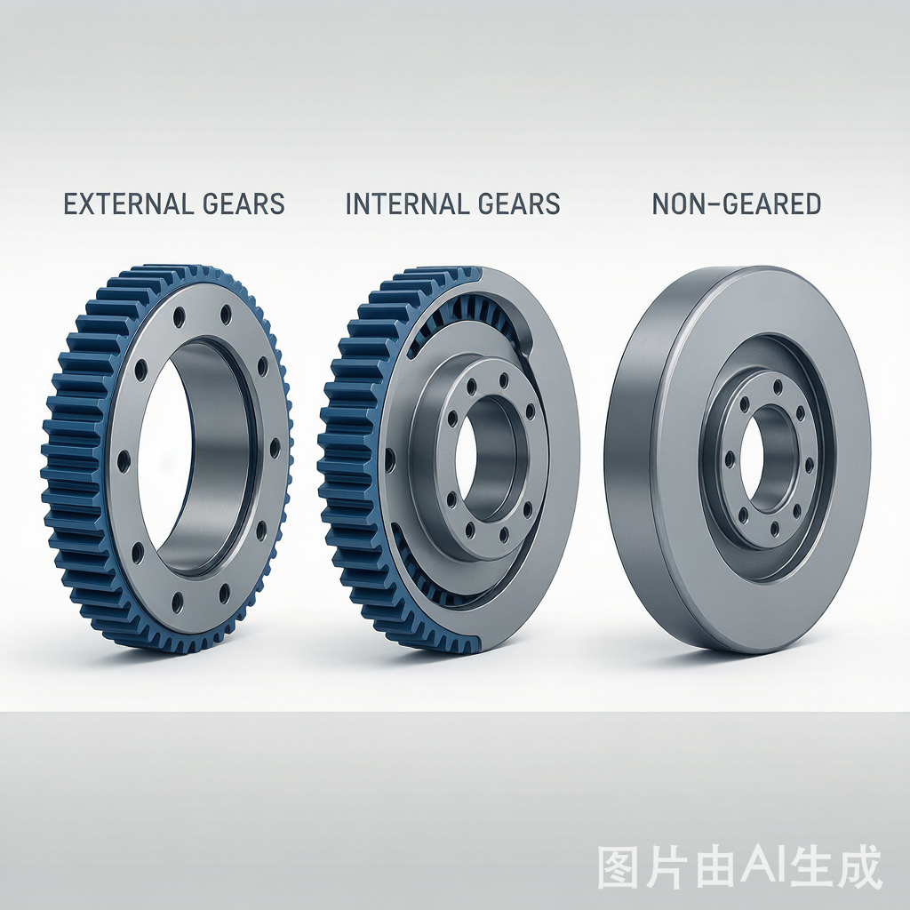
The gear on a slewing bearing is what rotates the assembly. Your choice depends on the drive mechanism layout:
- External gear — teeth on the outer ring OD. Easiest to machine, most common in excavators. Pinion drive mounts outside the bearing circumference.
- Internal gear — teeth on the inner ring ID. More compact, better protection from debris. Used when space is constrained (tower cranes, robotic arms).
- Non-geared — no gear teeth. Used in free-rotation applications where an external drive system handles rotation.
Gear module (metric) or diametral pitch (imperial) must match your drive pinion. Standard modules range from 4 to 20 for most industrial slewing rings. Tooth surface hardening (induction hardening to HRC 50-60) extends gear life significantly in high-cycle applications.
Sealing Options for Harsh Environments
Slewing bearings often operate outdoors in dirt, water, and temperature extremes. Sealing is critical:
- Lip seals (NBR) — standard, good to 100°C, oil/grease retention
- FKM (Viton) seals — high temperature (200°C), chemical resistance
- Felt seals — traditional, moderate dust protection
- Labyrinth seals — non-contact, high speed, no friction heat
- Dual-seal systems — labyrinth + lip seal for mining/offshore
For marine and offshore applications (corrosion class C5), specify stainless steel rings or heavy zinc coating (Zn/Ni) plus FKM seals and grease nipples with check valves.
Common Slewing Bearing Failure Modes
| Failure Mode | Cause | Prevention |
|---|---|---|
| False brinelling | Vibration without rotation (transport, idle equipment) | Rotate bearing periodically; use anti-fretting grease |
| Raceway spalling | Overload or fatigue beyond L10 life | Verify load curves; apply adequate safety factor |
| Gear tooth breakage | Pinion misalignment or shock load | Proper backlash setting (0.03-0.05 × module); shock dampers |
| Seal failure / contamination | Ingress of water, sand, cement dust | Upgrade seal type; increase relubrication frequency |
| Bolt loosening | Insufficient preload or vibration | Use torque wrench; apply thread locker; periodic retorque schedule |
Conclusion
Selecting a slewing bearing requires careful analysis of load conditions, gear requirements, environmental sealing, and mounting specifications. The upfront engineering time pays for itself many times over in extended service life and reduced downtime. For application-specific load calculations and cross-section recommendations, contact Boret’s engineering team — we provide free pre-selection support for OEMs and end-users worldwide.